Common Operator Info

|
Documented Operators
Common Operator Info |

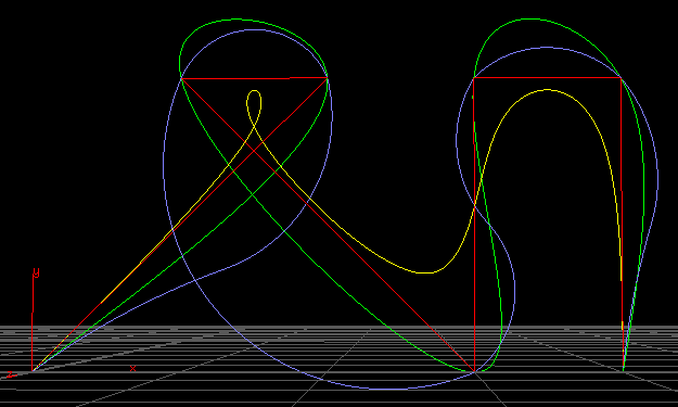
red=input yellow=b-spline green=convergent-spline blue=power
Without an input, the curve is currently a nearly straight line in Y, starting at origin.
For Basis interpolation, Converge can be used to coerce the curve into passing through the control points while still retaining full continuity. Otherwise, a Basis Spline will tend to shrink away from its control points. The number of Iterations will limit how many adjustments can be made towards a solution, stopping early whenever the path of the spline solution can stay within the given Threshold away from the control points it passes.
For Bezier or Power interpolation, activating Bisect will impose a halfway point between each incremental pair of input points. The halfway point is placed at the proper matrix-square-root position (or Bezier equivalent) but has a normal that is the simple average of the pair of input points. This may encourage the result to better retain the character of any sharp turns.
Also for Bezier or Power interpolation, using Blend will expand the influence to include input points outside the two adjacent points. The Blending adjusts the amount of this influence. This may help round out any tight corners, but excessive blending may exaggerate the curvature.
The spacing of output points is determined by a Method of either Length or Count. With an input surface, this method determines whether to use the Segment Length to directly set the spacing or to divide the full length evenly along of specific number of Segments. Without an input surface, both the length and count are used to create a line along the Y axis, starting at the origin. When using the segment length method on an input surface, the Tweak option will try to adjust the length in order to avoid having a noticably different length on the last segment.
A non-zero Linearity will cause the result to be closer to a result of linear interpolation. If Linearity Attr In (or Out) matches a real point attribute on the input, the linearity is altered by that attribute leading in (or trailing out) of each input point. The attribute linearity and the global linearity is combined using the product of the additive inverses.
If Min Dist Attr In (or Max) matches a real point attribute on the input, the sum of lengths of the output segments created between each input point and the preceding point is adjusted to conform to the given minimum and/or maximum.
Turning on Show Interpolation can add visual feedback of the interpolation process, where supported.
Web page, Copyright 2008-2021, Free Electron Organization