Common Operator Info

|
Documented Operators
Common Operator Info |

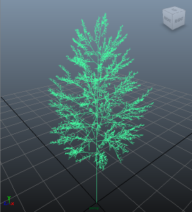
Quaking Aspen in Maya |

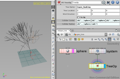
Colliding L-System in Houdini |

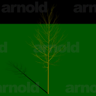
Quaking Aspen as a direct Arnold procedural |
This node contains the original implementation of the 2008 IEEE CG&A paper "Fast Simulation of Realistic Trees".
If there are multiple disconnected structures, they are treated as separate plants. In this way, an entire field of bushes and grass can be simulated with one node.
When on the first frame of scene (determined by the tool you are running in), the node always resets the simulation and rereads all the positions. The positions are not re-read on other frames. If you are on the first frame and making changes to the input or the parameters, the node will reset with each frame, which takes extra time. If you are on a different frame from the first, the simulation will advance with each change, even if you stay on the same frame.
If no Input Surface is connected, the Tree Name is used to load a procedural growth definition. In this case, the Output Surface is purely generated.
An optional Collider Surface provides an arbitrary barrier to collide against. Intricate concave surfaces can be problematic, so it can be helpful to convert the collider to as simple of a form as possible that still provokes the desired response needed.
The Wind Direction specifies a uniform velocity field for wind. The facing area of each branch segment affects the response, so the force applied to each segment is not the same. The magnitude of the Wind Direction describes the intensity.
Toggling Y Is Up off can switch from presuming a world vertical on the Y axis to one along the Z axis.
In Houdini, activating Output as Payload will create a custom primitive instead of outputting regular native geometry. Currently, this has no effect outside of Houdini.
Choosing to Write Radius will add a real point attribute with the generated radius at each point.
The Tree Name specifies a tree definition to load. Currently, this will be a '.rg' file in the 'vegetation' subdirectory of the media path.
The Branch Form indicates how the tree branches should appear geometrically in the output: None, Line, Cylinder, or Curve. Likewise Leaf Form indicates how the leaves should appear: None, Point, or Circle.
The real point Radius Attribute provides a radius at every point in the input. If a radius is not provided, it will be computed with the Area Ratio Power. Technically, this is the logarithm to base 10 of the ratio of the base cross-sectional area of a stem to its length. That definition was chosen to give a fairly linear dial that is easy to adjust. But, in practice, all that is important is that high numbers like -3 tend to be more stout, like trees or saplings, while lower numbers, like -4 or -5 tend to be more supple, like weeds or grass.
The vector point Velocity Attribute allows for a detailed wind field. The Wind Direction, if non-zero, would be added to this value to determine a unique velocity at each point in the plant. The velocity values are re-read for each frame even though the position values may not.
The real point Rigidity Attribute will scale the stiffness for each point in the tree. An inherent stiffness is determined from the length and radius at both ends of each segment. The attribute values merely scales the computed values. A Uniform Rigidity scales all the computed values after the attribute scaling, if provided. The rigidity values are only recomputed during the reset at the first frame of the scene.
The Uniform Damping can be used to bleed energy out of the simulation. Since the semi-implicit solver used inherently loses energy, a non-zero value tends to add a sluggishness that is usually not desired.
A vector point Target Attribute is like the position attribute, but specifies a goal where you would like the points to be. An integer point Targeted Attribute is effectively a boolean, specifying which points are to be targeted. Untargeted points will ignore their target positions. Both of these attributes are re-read for each frame.
Input geometry is converted into a whole different form in the solver space, which can lead to imprecision and cumulative deviation when bought back to conventional geometry. Using Angle Compensation will determine the approximate imprecision due to angular recombination and adjust rest angles to help alleviate the issue. Correction will look at the end result of the twice-converted structure prior to simulation and store fixed adjustments to apply to the output after every simulation step. Both of these values are generally left on.
The Collision Method determines how each tree impacts that surface and how it should respond. The Bounding Sphere method is simplest, computing a minimal sphere containing the entire surface and pushing any penetrating segments outward from the center. The Partition Sphere method is similar, but if computes a separate sphere for every part in the collider. Interpenetrating spheres are treated elegantly and this method can produce very smooth responses, even to a variety of otherwise troublesome pinching situations. But setting up a collider for sphere partitioning can take a little effort. The Impact Radial method does 'nearest point' searches on the collider surface and pushes penetrating segments outwards from the computed center of the surface. The Impact Normal method also does 'nearest point' searches, but pushes away from the surface using the surface normal at the point of impact. While this is the most intuitive notion of how to collide with an arbitrary object, intricate concave surfaces can easily lead to jittery pinching situations.
Using Collide With Segment Ends will force the collision system to only consider the endpoint of each segment during collisions. Otherwise, a contact point is determined along the length of each segment. Computing the contact point can be better for small colliders on large plants, like trees. But for larger colliders, relative to the plants, such as walking through grass, it might be best to keep this turned on.
When using the Partition Sphere method, the primitive string Partition Attr specifies which faces of the collider belong to each part, determined by which primitives have matching strings. While it would be permitted to just use some pre-existing distinction, perhaps already named parts like "forearm", "hips", "neck", etc, a more deliberate approach might be to create a bunch of uniquely named spheres manually and then wrap them to the animated skin or skeleton of your colliding character (or whatever).
The Collision Threshold specifies the minimum distance you want each segment away from the collider. This distance is not guaranteed. The internal algorithm has a strong preference for stability and smooth natural motion over stubbornly keeping clear of collisions.
The responses from collisions are scaled by the Reactivity. In theory, this should be set to one, which would not scale the responses, but reducing this value may alleviate an overly excited plant in a difficult collision situation. However, a reduced reaction can noticeably increase collider penetrations in the output.
A non-zero Depletion causes a ongoing reduction of branch segment motion near a collision surface. This effect is ramped down to zero over the Falloff distance, away from the collider.
A non-zero Repulsion pushes away branch segments near a collision surface. This can be used to portray the effect of crowded plants pushing on each other. This effect is ramped down to zero over the Falloff distance, away from the collider.
A non-zero Wind Hampering reduces the effect of wind near a collision surface. This effect is ramped down to zero over the Falloff distance, away from the collider.
When Plastic Collisions are on, the Plasticity determines how much of any prior collision response is retained in each following frame, even if the collider has moved away.
No production testing in Maya.
Arnold support is very preliminary.
A stand-alone viewer is also available.
Web page, Copyright 2008-2021, Free Electron Organization