
Common Operator Info
|
|
Documented Operators
Common Operator Info |
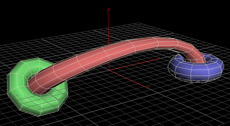
rope tie between two rigid grommets
This can be useful in lace-up garments like corsets and footwear.
If actual physical grommets or buttons are used, the SurfaceBindOp and SurfaceWrapOp can update those grommets as well as provide the locator data that the ClaspOp requires.
A required Reference Surface should be the same geometry provided at a fixed position, usually the unanimated modeling pose.
A optional Collider Surface can be provided for each deformed clasp to avoid.
String point attributes on the input surface given by Locator 0 and Locator 1 specify which two locators to use for each point. If these attributes are empty for a point, that point will not be changed.
By default, the deformation of each tie is restrained in order to maintain a taut appearance. However, the suppressed influence of the locator motion can be reintroduced. With the default of a zero Tangent Influence, the tangent axis of the locator transforms is replaced by the line between each pair of locators. A non-zero tangent influence restores some or all of the original locator tangents, usually evident as more active tilting near each end point towards and away from the opposite endpoint. A zero Normal Influence will use the average of normals on each pair of locators as the driving normal for both locators. A non-zero normal influence will keep some or all of the individual locator normals, usually evident in the twisting around the axis connecting each pair of locators.
If a collider surface is provided and Collision Avoidance in on, an arching effect will be applied when collisions are detected. The magnitude of the arch will be between Arch Min and Arch Max. The minimum of zero is reasonable so that there is no arch added when no collisions occur. However, this setting can be useful to interactively examine what arching can do or as a way to always start with a little imposed arch to reduce the activity of light collisions. Lowering the maximum can be used to avoid excessive deformations as well as reduce the solution space to improve precision.
To avoid undesired collisions near the endpoints where the clasp tie may naturally penetrate the underlying surface, the Dead Zone can be used to ignore collisions for a unit distance from one locator towards the opposing locator. The maximum value of 0.5 describes a combined zone reaching halfway across the span from each locator, thus meeting at the midpoint and eliminating all collision response.
The output data can be pruned using Discard Locator Attr, which removes the point attributes which named the pairs of locators. Additionally, Discard Locators will remove the actual locator data stored in detail attributes.
 PROTOTYPE
Web page, Copyright 2008-2021, Free Electron Organization